Sea Turtle Remote Observation Camera
Housing
Sony network camera

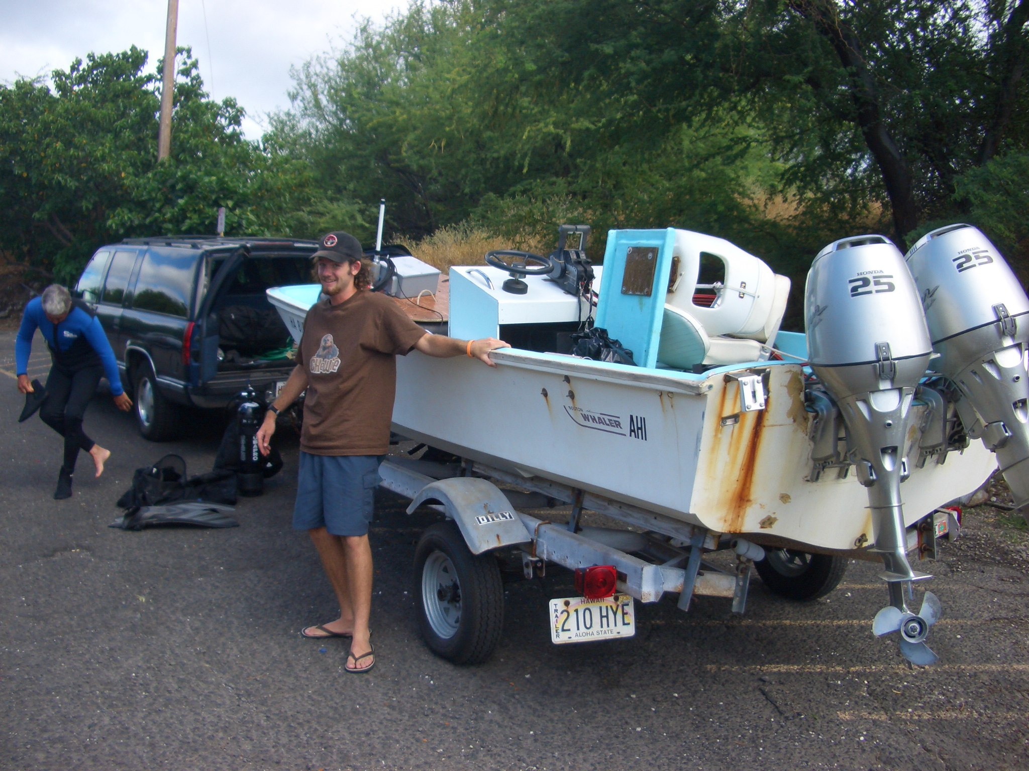
This June I returned to my high school in Hawaii for a vacation. I got bored after a while, so I met up with my friend Marc Rice to work on a fun project.

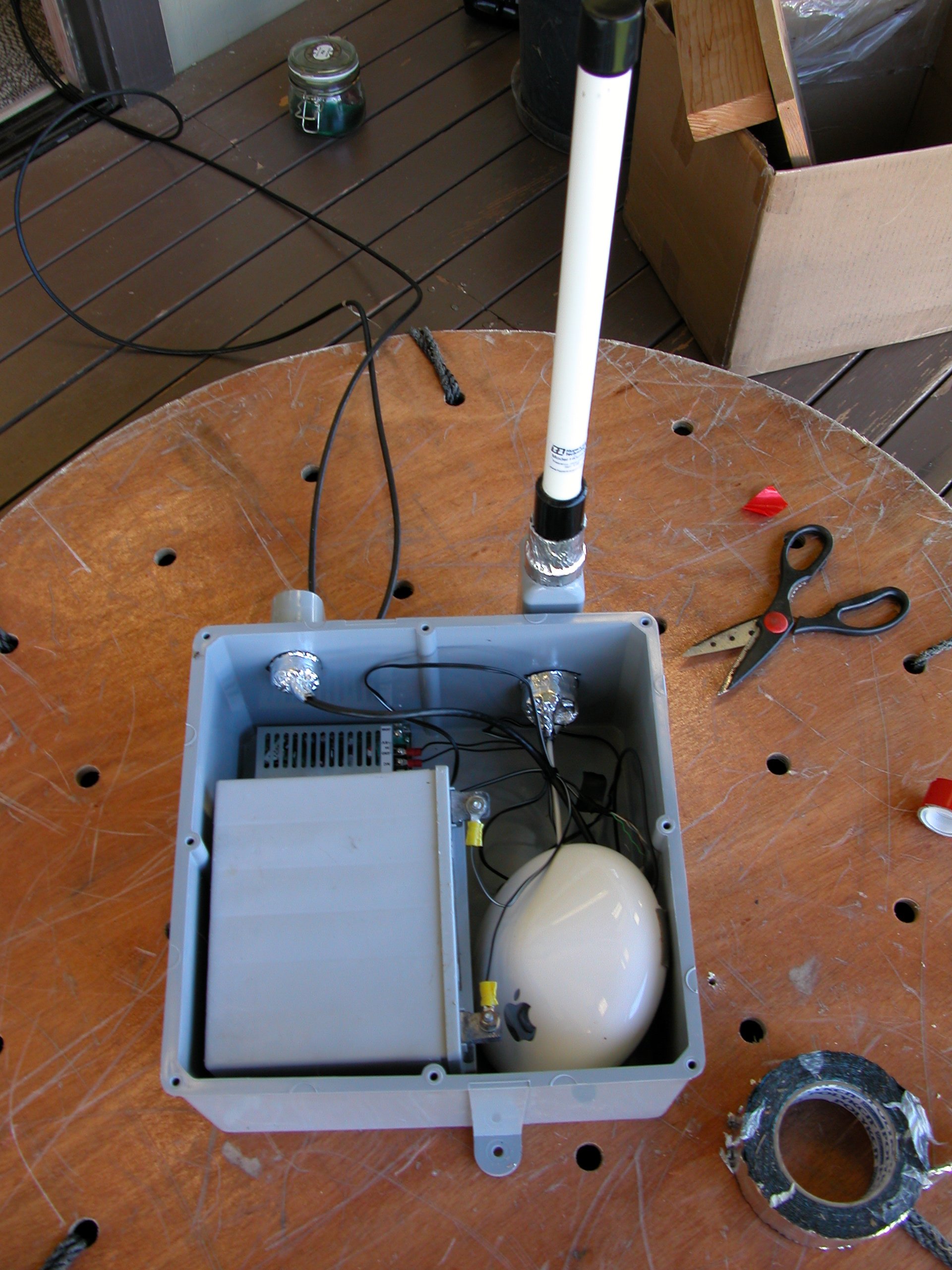
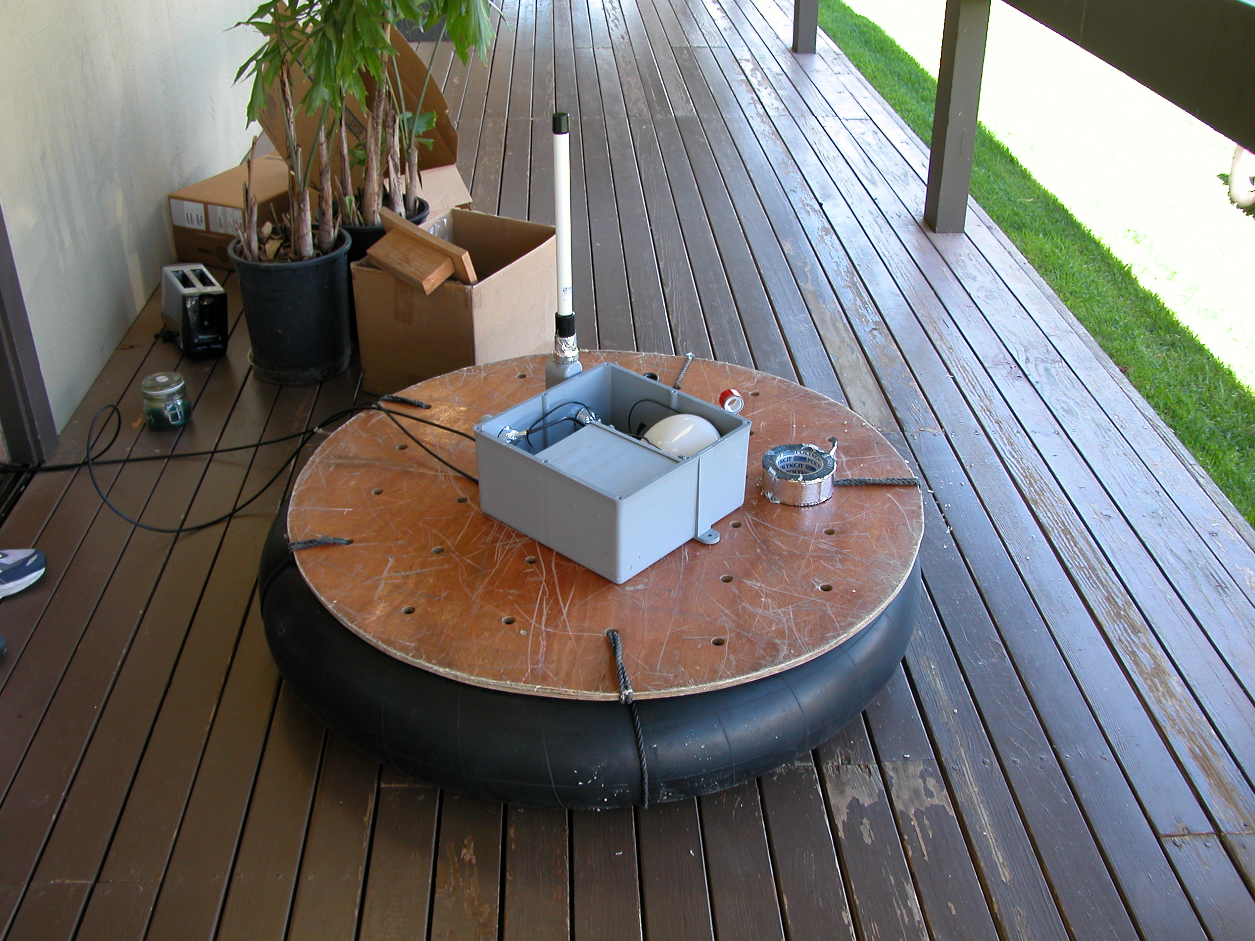
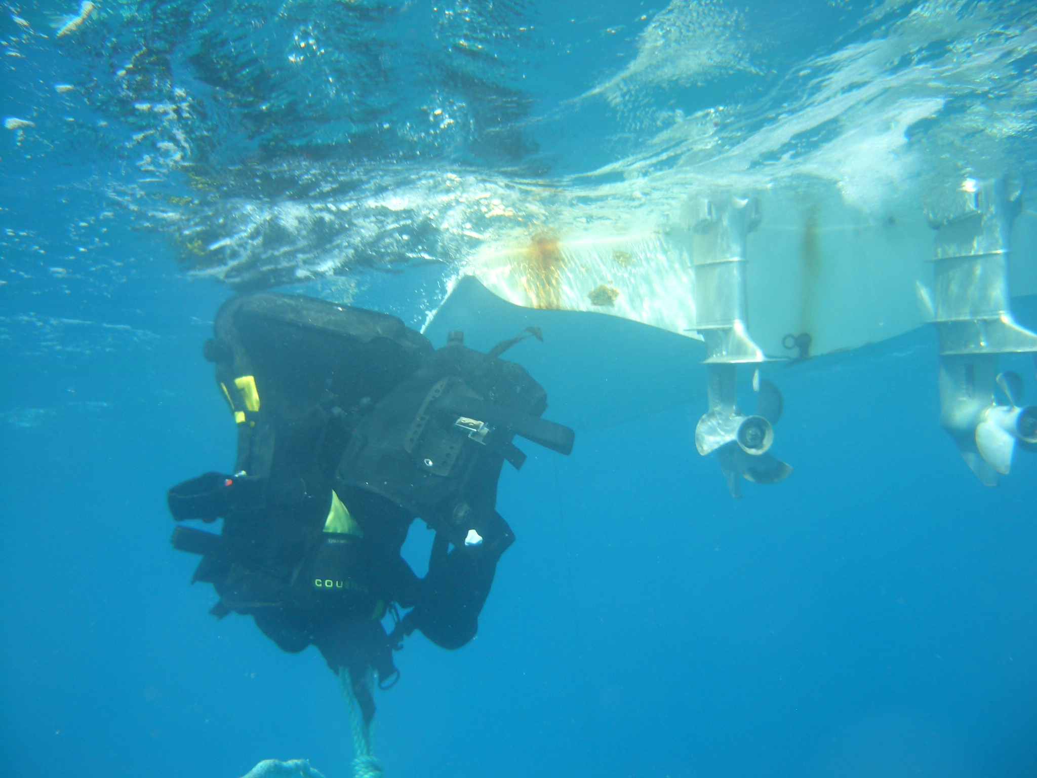
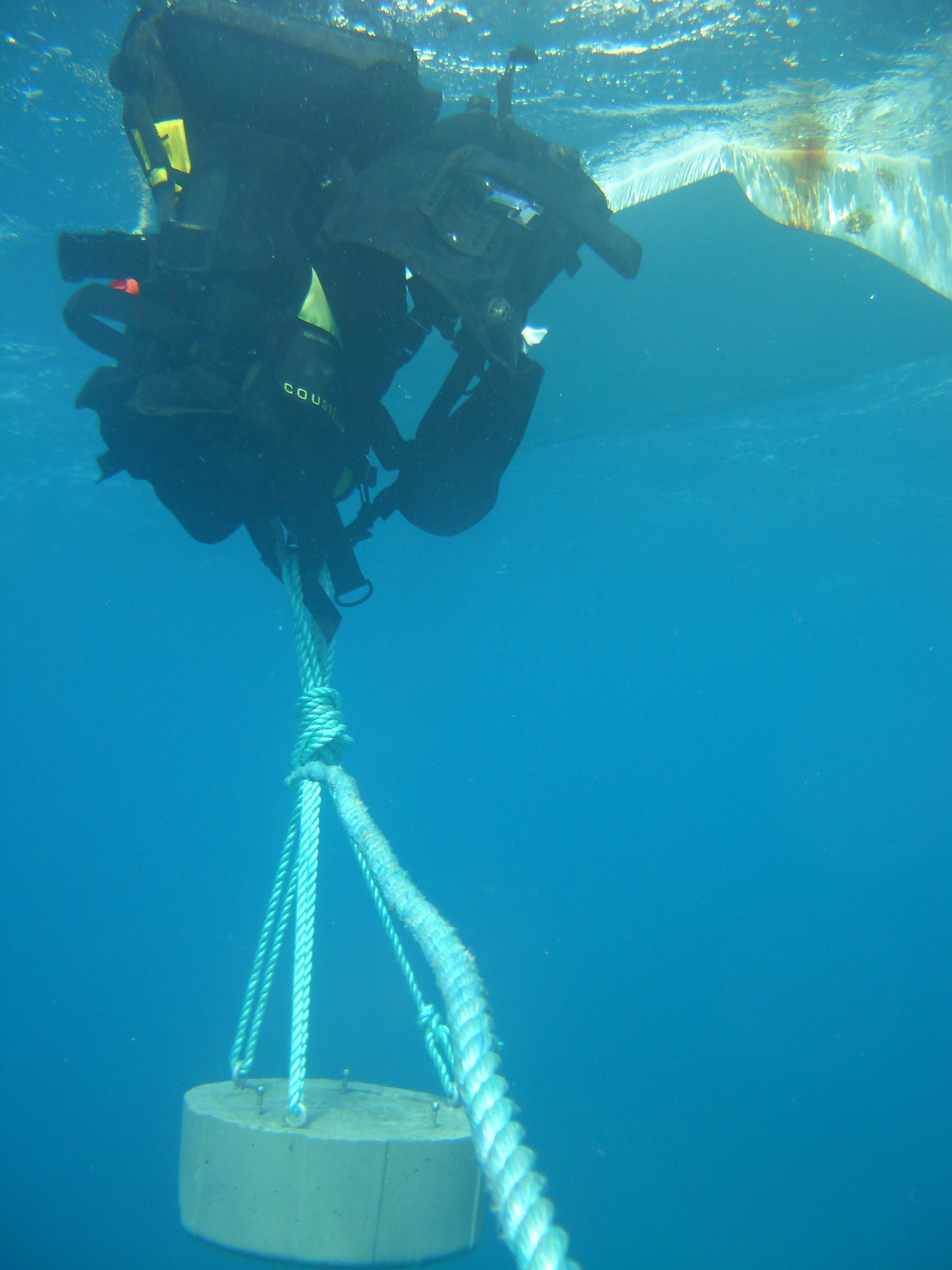
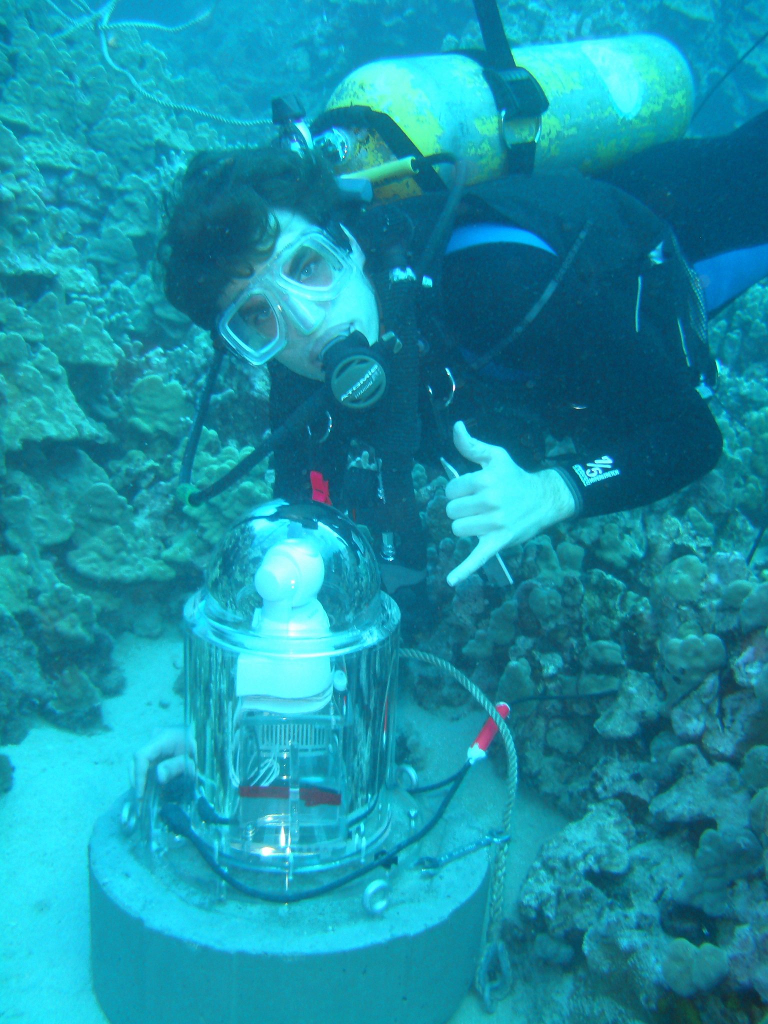
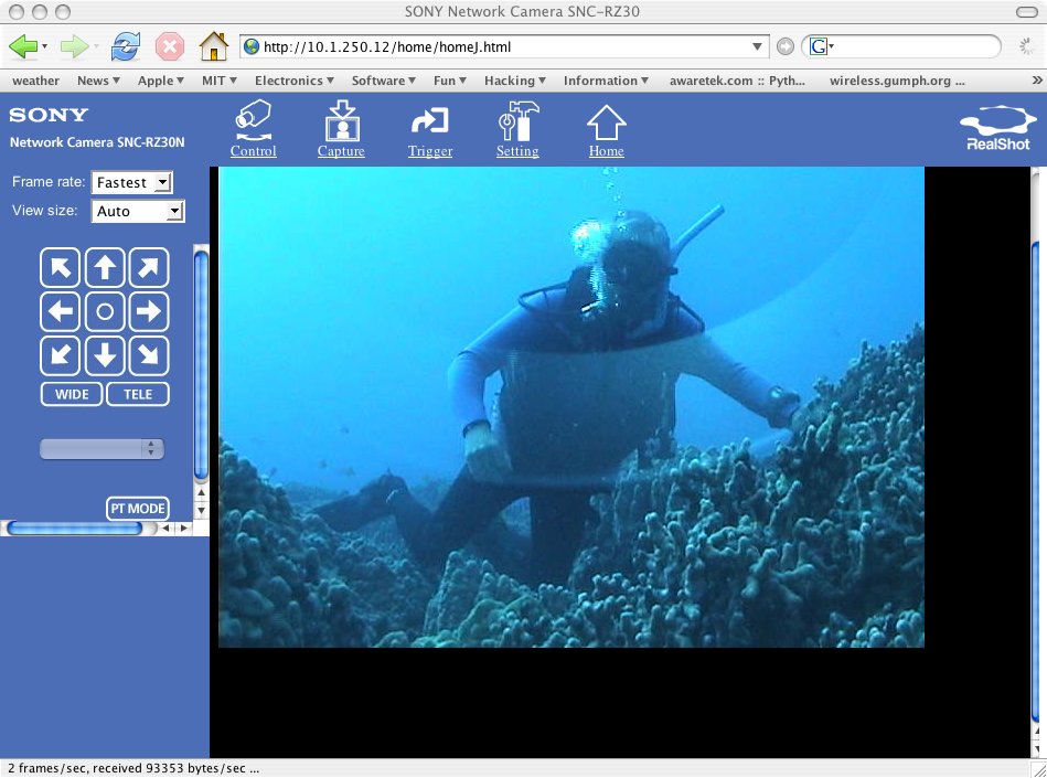
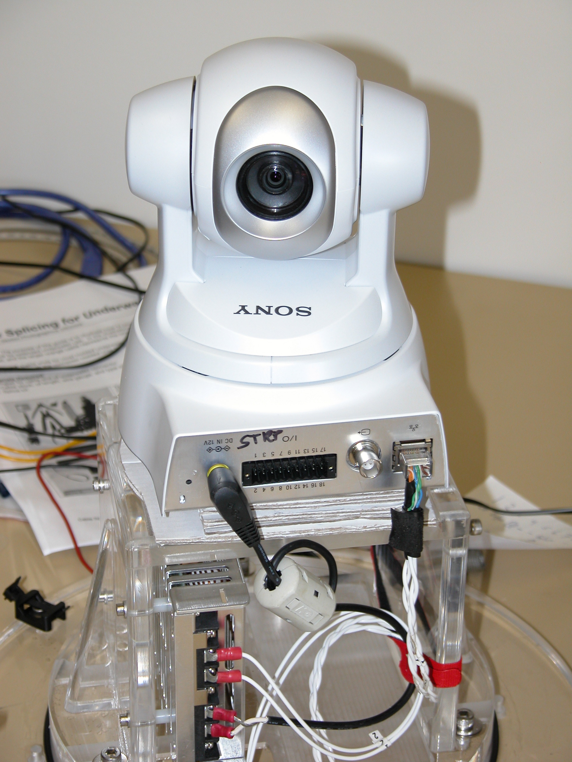
A while ago we worked together installing several remote cameras in neat locations for turtle observation. We often talked about how cool it would be to set up something underwater to observe a turtle cleaning station. In my absence, he had Sexton Photographics build us a custom housing for the Sony SNC-RZ30N network camera we'd used in the past. So, when I came back to Hawaii, we were excited to work together deploying the housing in the field.

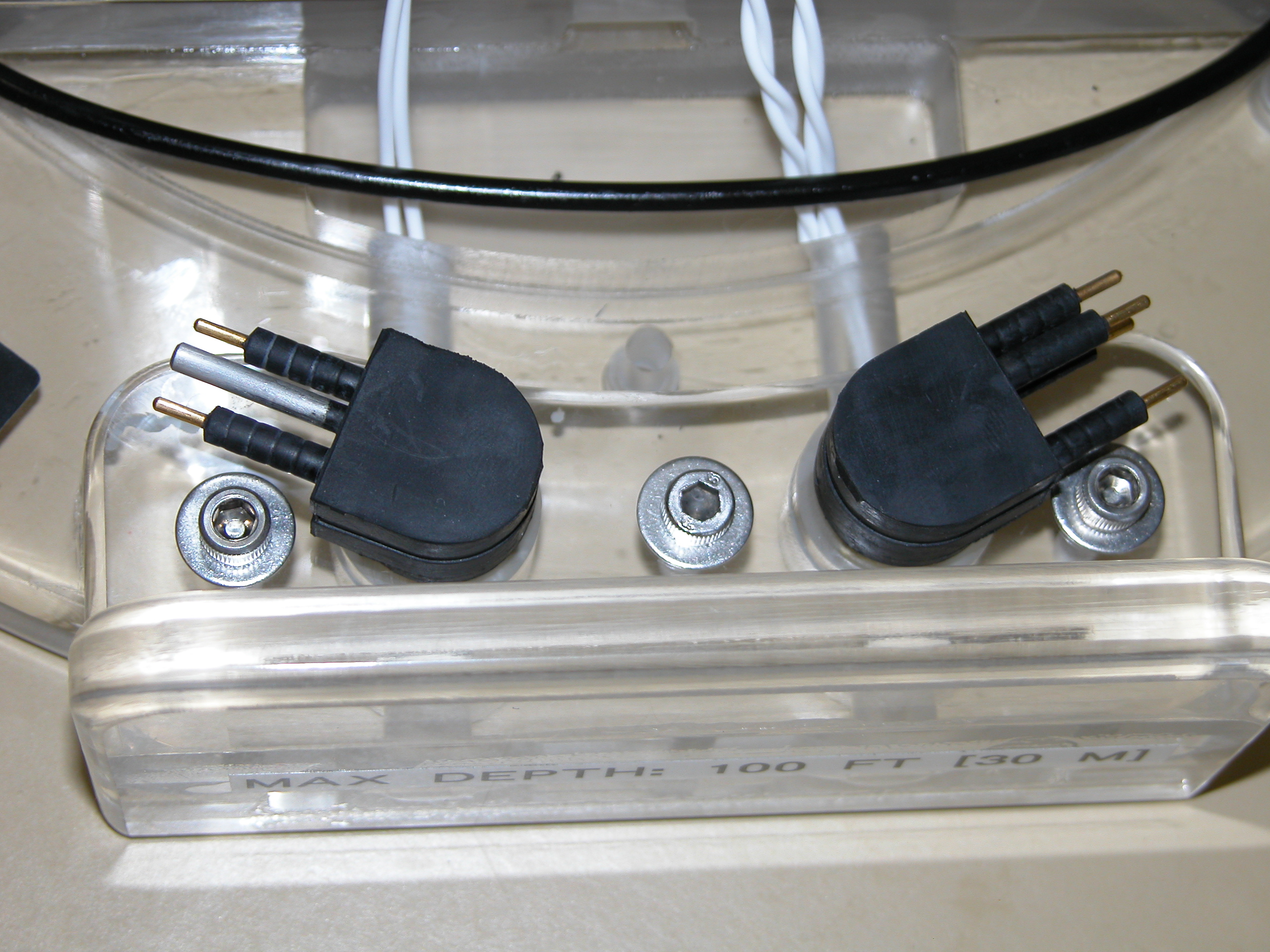
The housing is rated to 100 feet and has wet-pluggable connectors. There is enough space in the interior of the housing for a power supply (9V-15V input, 12V output) and a battery, if desired. Overall, we found the housing to be very well built and robust, although there are a few design changes I'd make for the next version.

Surface Buoy

To provide network connectivity to a camera that is deployed in 40 feet of water 1200 feet offshore, we use a solar-powered surface buoy with a wireless access point.

Shown to the right is the waterproof enclosure (found at a local hardware store) we used on the surface buoy. It contains a 12V lead-acid battery, an Apple Airport Extreme, and a 5V power supply (the Airport runs on 5V).

To seal the box where the cable enter the box, we use 90 degree pipe fittings PVC cemented to the outside of the box. A 1" fitting is perfectly sized to fit around the base of an 8dB omnidirectional 2.4ghz antenna, so this provides a convenient weatherproof antenna mount. For further waterproofing there are rubber stoppers wrapped around the cables as they pass from the fitting to the box.

The box is then bolted to a sheet of plywood, which is tied with ropes to a durable rubber inner tube. Ths provides a wide base, plenty of flotation, and simple rigging to the anchor. Ultimately we plan to add an LED to the top of the antenna to make the buoy more visible at night. The buoy is connected to the camera housing by an outdoor weather-resistat CAT5 UTP cable. Two pairs of the cable are used for power (at 12V) and the other two pairs are used for ethernet.

Waterproof box on buoy
Complete buoy

We quickly ran into a problem trying to splice the CAT5 cable to the pigtails attached to the wet-pluggable connectors for the housing. The pigtails are 20AWG stranded wire, untwisted. This causes a big problem with ethernet transmission, because ethernet is not very good at tolerating impedance mismatches in cables. The twisted-pair CAT5 has an impedance of about 100 ohms (at 100MHz), whereas I estimate the stranded wire has an impedance of over 150 ohms. This major impedance mismatch causes reflections when the line is driven, which makes reliable data transmission impossible.

After perfecting my solder joints on the splices, twisting portions of the pigtail wire, and doing everything else I could think of that might possibly help the situation, it still wouldn't work--a 100 megabit link could be established, but then would immediately fail. It occured to me that reflections wouldn't cause as much of a problem at 10 megabits, and the camera would still work effectively with the speed limitation.

Sure enough, forcing the link slower fixed the problems. So, I reconfigured the Airport Extreme to force the WAN port (for some reason you can only set the link-level parameters for the WAN port, not the LAN port) to 10 megabits.

Wet pluggable connectors
Concrete Base
Base parts

To keep the camera stable underwater, we built a heavy concrete base to bolt the housing to. First we copied the bolt pattern onto a wooden template and mixed up a batch of concrete. Using a trash can as a mold, we poured a base with 120 lbs of Quikrete.

Then we embedded stainless steel bolts to secure the camera housing. We also added eye bolts (only available in galvanized) to rig a carrying system to so we could use ropes to move the base around.

To more strongly embed the bolts in the concrete we used large fender washers--without this the bolts would be inclined to pull right out. To keep these in place while the concrete is setting we twisted bits of wire around the non load-bearing side of the fender washer.

Wire nuts
Concrete reinforcement with wire

To further strengthen the base we cut up a wire grid and set it inside the concrete. There isn't really a science to this.

After pouring the concrete and inserting the bolts and the template, we carefully aligned the bolts vertically and adjusted the height of all of the hardware.

Base template
Finished base

The finished base! Very heavy, very solid, and fitting the housing bolt pattern perfectly.

Deployment

Next we found a good site to put the camera at and deployed it temporarily for more thorough field testing. Unfortunately, the only day we had time was very windy and rough, which made for some interesting challenges deploying. We recruited Ben Honey to help us out in the water.

Gearing up
Using BCs as lift bags

We couldn't find a lift bag, but we did find a bunch of leftover BCs (buoyancy compensators, used by divers). So, we tied a bunch of them together, attached them to the base, filled them all up, and tossed the base overboard. We found that only about 1.5 BCs of buoyancy was necessary to lift the base, and we slowly let air out until the whole rig was neutrally buoyant.

To suspend the base we used a three-point anchoring technique borrowed from rock climbing.

Next, we wrapped a line from the base around the anchor line and let a bit more air out of the BCs. With help from a person on the boat, we slowly slid the whole rig down the anchor line towards the final location.

Once the base was set down and untied, one person wrangled the camera in its housing down from the boat (it is very positively buoyant), and planted it on the base. Another person then bolted the housing down.

Rigging the base
Camera in its final location

After bolting the camera down, we connected up the cables and headed topside to see if it worked.

Results

Here is a screenshot of the camera's web interface, in all its glory.

Using a laptop in heavy wind and surf was a bit nerve-wracking, so after a few minutes of testing, verification, and high-fiving we put everything away, recovered the camera, and headed back home.

Camera screenshot
Conclusion

Over the course of the project we had some insights about things that we could do better on the next version of the system. Mostly we were fairly satisfied with the result, but there are a few possible features that could be added or improved.

  • A fiber-optic interface. This would eliminate the ethernet impedance matching problems, significantly increase range (so we would have the option of deeper depths or even running the cables all the way to shore). Fiber media converters would be used to interface to the camera.
  • Higher cable power voltage. Running the power at 24V or 48V would increase range and robustness. Power supply bricks would be used to drop the voltage down to the 12V required by the camera.
  • Smaller housing volume. Making the housing less positively buoyant would make it much easier to handle underwater.
  • Handles. Large handles on either side of the housing would also make it easier to handle.
  • Deeper depth rating (150-200 feet). The current depth rating of 100 feet excludes a few sites that could be very interesting for observation.

Valid XHTML 1.0! Valid CSS!